|
Quickstart Wiring Guide
AFR Gauge Remote Control Instructions
Boost Gauge Remote Control Instructions
Oil Pressure Gauge Remote Control Instructions
Oil / Water Temperature Gauge Remote Control Instructions
Quickstart Wiring Guide
D1-BOP-WBA-M Dual Vacuum-Boost & Wideband Air-Fuel Ratio Monitor
D1-OPM-OTF-M Dual Oil-Pressure & Oil Temperature Monitor
D1-OPM-WTF-M Dual Oil-Pressure & Water Temperature Monitor
D1-OTC-WTC-M Dual Oil Temperature & Water Temperature Monitor (Celcius)
D1-OTF-WTF-M Dual Oil Temperature & Water Temperature Monitor (Farenheit)
D1-PYC-WBA-M, D1-PYF-WBA Dual Pyrometer / Exhaust-Gas Temperature & Wideband Air-Fuel Ratio Monitor
LC-1 Digital Air/Fuel Ratio (Lambda) Sensor Controller Manual
Please be aware that these tips are provided for your reference only and podi.ca is not liable.
Part 2 and 3 of following installation guide is courtesy of a4mods.com and can also be found here.
Installing an Analog Podi Boost Gauge
Part 1: Installing the vacuum line
Part 2a: 1.8T Engine: Connecting the Boost/Vacuum Line
Part 2b: 2.0T FSI Engine: Connecting the Boost/Vacuum Line
Part 3: Connecting the Anti-Buzz Fitting and Wiring the Gauge
Prior Experience: None
Cost: approx $250
Time: 1 hour
SUPPLIES for Installing the Gauge - Pretty much all of the parts you need are included in the gauge package. I made use of some additional wiring to extend the Podi harnesses. You may not needed these on your install, but I used them on mine.
- Podi Gauge and Pod Package
- T8 Torx screw driver with long/thin neck (This one from SEARS works, $5)
- Various electrical connections, tape, etc ($5.00)
- Metal Coat Hanger
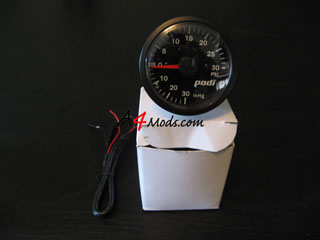
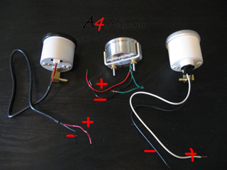
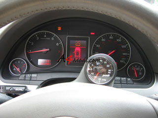
In this writeup we will be installing 3 different gauges offered at Podi.ca The three different gauges are pictured here:
VEI Systems digital boost/vacuum gauge in RED.
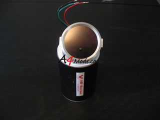
Stewart Warner package - this guage has a custom dial and needle to match the Audi Interior.
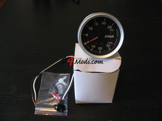
Podi's new prototype gauge.
This is where your knee bolster is located
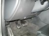
Pop off the fuse panel cover on left end of the dashboard by instering a small flathead screwdriver into the notch and and gently pop the cover open, then with your hands you can carefully pop the rest of the cover off.
There are 3 8mm bolts that fasten the bolster to the dashboard. One of them is on the fuse panel left end of the dashboard.
The other two bolts are on the left and right sides fo the bolster below the steering column.
One the bolts are removed the bolster is held in place by some friction clips. Reach below the bolster and gently pull forward and you will see the bolster break away from the dash.

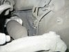
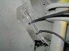
After removing the knee bolster and looking for a grommet to pass the line through. I found a big grommet that has 7 openings on it and 2 of them are already used.
You can see the grommet in the center of these pictures
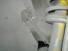
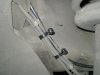
Now you need to jack up the driver side of the car and remove the wheel. Once the wheel is removed you will see the other side of the grommet.
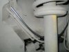
If you look on the other side of the wheel well there is another grommet that accesses right into the engine bay and directly under the intake manifold where the boost line you want to tap into hangs.
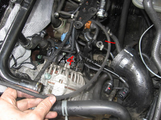
I chose the 3rd nipple on the bottom row as it was the closest to the size of the vacuum tube. I snipped the tip of it off and also made a small slit on the top to allow for the tapered end of the nipple to expand if needed to accomodate the tubing as I fed it through from the inside
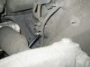
Feed it past any cables and into the engine bay
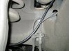
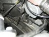
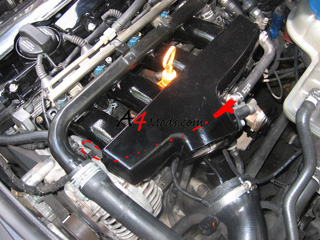
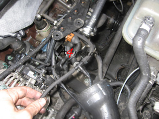
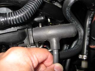
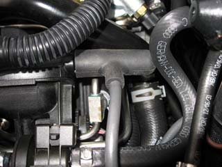
The stock vacuum hose is connected to the intake manifold where it is circled in red
Detach the stock vacuum hose from the intake manifold. Cut 2.0” off the end of the boost gauge hose that you fed into the engine bay.
Using the enclosed t-fitting connect the center arm to the boost gauge hose that was fed into the engine bay. Connect one of the arms to the stock vacuum hose and the remaining arm to the 2.0'' piece of vacumm tube which finally connects to the intake manifold. Use the zip ties to secure the vacuum lines to the fittings.
Secure the vacuum tubing to the existing lines so there is no way it was going to move around and trim it up
Put the driver side wheel back on and lower the car back on the ground.
You can now plug the vaccum line into the back of the boost gauge and test the operation of the gauge at this time by starting the engine. You
should see ~20 inHg of vacuum at idle.
This small section describes where to connect your Boost/Vacuum Line on a 1.8T engine.
Installing the gauge is not very challenging. The first thing you need to do is find out where to tap to get a good boost reading. I used this line off of the intake manifold.
On my vehicle, this line runs under the intake manifold. You can tap it anywhere along the way, but I wanted the tapping point to be out of site. I drew in red the path the boost/vacuum line takes.
The T represents approximately where I T'd into the line.
I was working on my car doing a couple other things when I installed this gauge, so in this picture my intake manifold was removed. This give you a better idea of where this boosted line runs.
I cut the line approximately where the red line is drawn.
With the line split, you can install the supplied T fitting. I used a little bit of dish soap on the plastic part of the T fitting to get the hose to slip on easier.
If you have a 2.0T FSI engine, included with your gauge will be a custom silicone piece for connecting your boost/vacuum line.
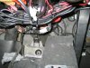
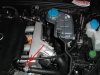
Remove the engine cover and if you look along the right hand side of the intake manifold there will be a small black rubber cap held in place with a clamp. Cut the clamp, remove the small rubber cap and this will expose the bung that you will tap onto.
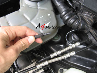
If you purchased the kit for a 2.0T FSI engine, then the kit will come with a custom silicon T-fitting for the install. The silicone fitting looks like this:
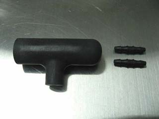
Take the silicone t-fitting and insert one of the anti-buzz inline restrictors into the center part of the fitting.
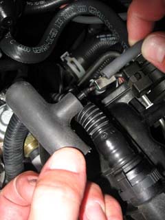
Connect the boost gauge line to the other side of the anti-buzz restrictor
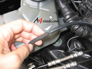
Push the boost gauge line as far as you can to make sure the vacuum line seals over the restrictor
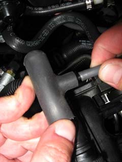
Slip the open end of the silicone t-fitting onto the exposed bung on the intake manifold and push the fitting in as far as possible
Analog gauges have a tendency to buzz when under boost. To preven this, you should install the anti-buzz fitting on the newly installed boost line. If you have a 2.0T, you have already done this, if you have a 1.8T, you just need to splice this fitting in.
After the T you just added, install some vacuum/boost line, and slip the fitting in the end:
Pop another piece of vacuum/boost line on the end of the anti buzz fitting to feed it into the cabin.
The goal is to have the anti-buzz fitting approximately 14 inches away from the connection to the gauge.
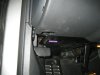
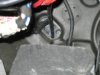
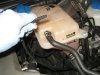
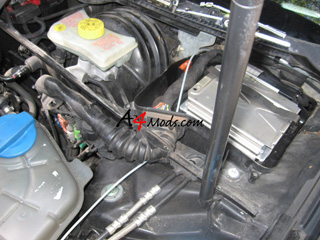
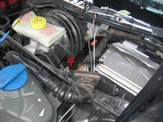
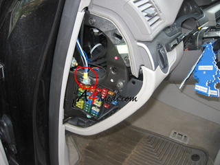
I decided to run the vacuum hose into the cabin by going through the ECU box. This gives a very easy, straight shot to the cabin. In order to do this, you need to remove the cover to the ECU box. There are only 5 Torx bolts holding in in place. I show how to remove the cover in the ECU Removal Writeup.
The picture to the right has the ECU cover removed
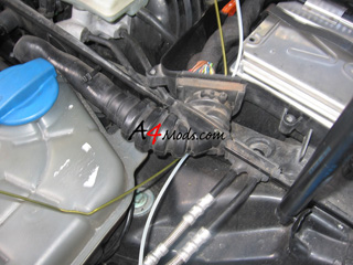
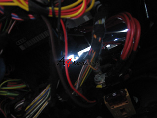
The path to the cabin is shown in the picture to the right by the white vinyl hose which I used for my old boost gauge. In order to get into the ECU box you need to poke through the rubber grommet/hose which has the electrical connections for the ECU, and then run the wires through it. There are a couple rubber nipples on the grommet which you can try to use, or you can just poke a new hole.
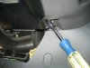
This is where your coat hanger comes in handy.
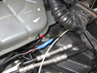
Unbend the coat hanger and poke it through to the ECU box a shown to the left
After the hanger is through, you can tape the vacuum hose to the hanger, and pull it though into the ECU box. I showed this same procedure using the wires for the electronic gauge below:
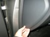
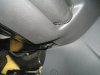
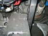
In order to get the sender harness into the cabin, you need to remove the lower kick panel on the driver's side. This is very easy, and I have this shown in the first few steps of the Turbo Timer Install.
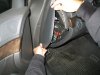
After the kick panel is removed, you can look up from the floor on the drivers side and see up and out of the ECU box. Here you can see plenty of daylight coming through.
Just slide your boost hose down through this hole so you can access it from under the steering wheel.
The one advantage of the analog guages is that they are very easy to wire. Each gauge only has one power wire, and one ground wire. The power and ground are labelled below for each of the three guages.
For a ground, I decided to use the same ground I have been using for all of my accessory installs. I just used a bolt next to the fuse panel. I sanded off the paint to it has a good chassis connection.
The black wire from the gauge, and the sender were grounded here.
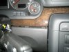
Powering the Gauge: The power for the analog gauges should be taken from your light switch. By taking power from the light switch, the gauge will dim as you dim your interior lights.
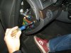
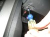
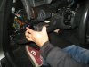
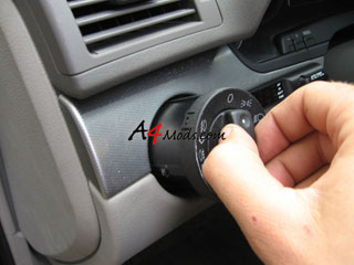
To get at this power wire, push your light switch inwards while it is in the OFF position
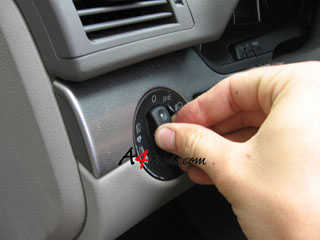
Turn it slightly to the right, between the OFF and the next position
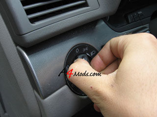
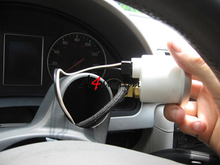
Pull the switch outwards
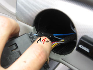
With the switch out, you need to find and tap into the blue wire shown to the right. It is on the left side of the harness.
This will be your power wire.
Depending on which gauge you are installing, you now need to run these power/ground wires up into the Podi and connect them to the gauge. Obvously you will have to run the boost line to the back of the gauge as well. When you are done, the back of the gauge should look something like this:
When the two torx bolts are removed, the upper cover will just pop right off of the lower cover.
You will see that there is some leather material attached to the upper cover. On my vehicle, there were 4 retainer clips on the underside of the cover which needed to be removed. Just work a small flathead driver in there and they will pop right off.
Push the gauge into the pod, and mount the Pod as discussed in the Electronic Stepper Motor Gauge install.
Here are what the 3 different gauges look like
VEI
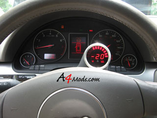
Stewart Warner
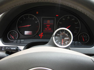
Prototype
Just because I know you are curious about the VEI digital gauge, I decide to take a short video of how it works when you rev the engine. It is actually much cooler/nicer than I thought it would be.
Short AVI video here.
Any other information you may need is located over on the Electronic Stepper Motor Gauge install.
|
| |
|
|
podi.ca 1726 Ross Road, North Vancouver, BC V7J1V7 Canada - phone: (800) 861-PODI (7634), fax: (800) 861-7634 - Terms & conditions: Podi.ca is not related to the Volkswagen/Audi AG, nor any other company mentioned on the site unless otherwise stated. All photographic material and or text on the podi.ca web site is the restricted / copyright private property of podi.ca or privately used with permission of the original owner. Patent Notice - Canadian Industrial Design No. 116788, European Community Design Registration No. 000570296-0001, US Patents: D538,720; D593,913; D593,914; D611,884 and other patents pending.
|